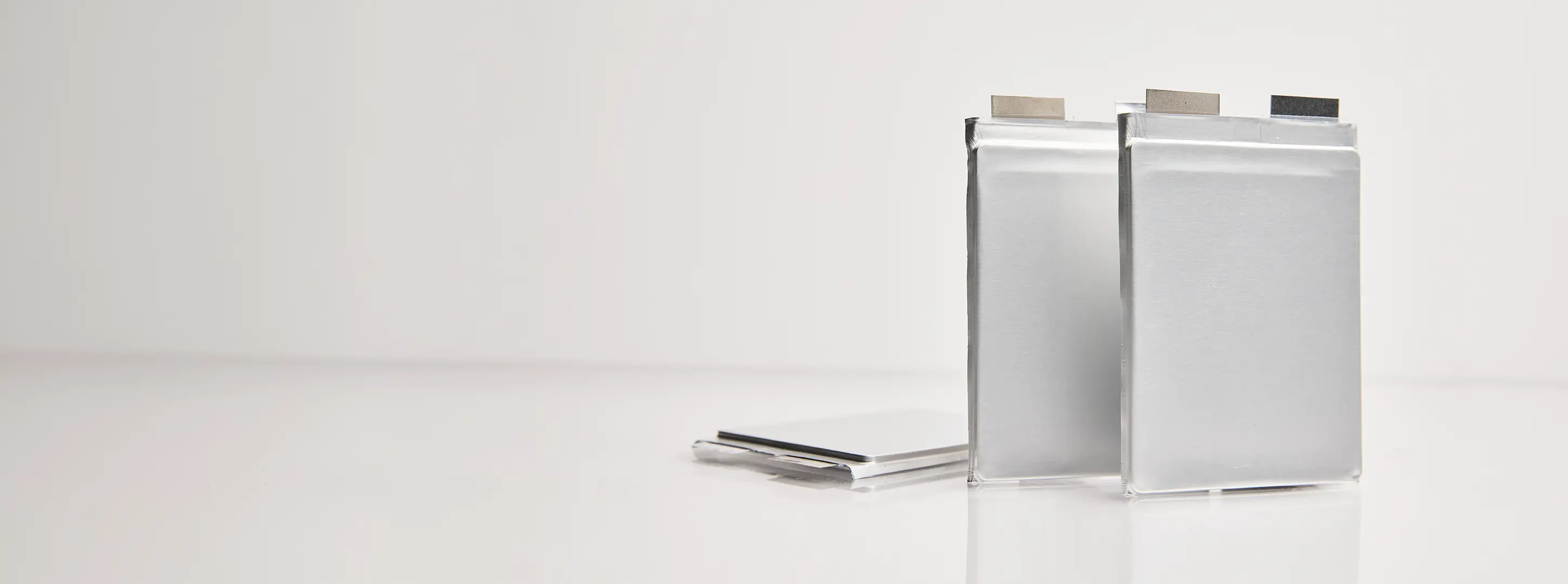
Learn more about our Osprey platform: consisting of the QS ceramic separator and anode-free cell design paired with a solid sulfide cathode.
Abstract: Sulfide-based solid-state battery approaches are widely popular across the battery industry. Their popularity is due to the high ionic conductivity of sulfide electrolytes and the relative simplicity of processing them. However, sulfide still face several significant limitations, including the need for high applied pressure, as well as poor cycle life and incompatibility with lithium metal. Using our Osprey platform, consisting of the QS ceramic separator and anode-free cell design paired with a solid sulfide cathode, we demonstrate an all-solid-state battery that can deliver 1000 cycles to 80% capacity retention under gold-standard conditions: 1C/1C charge/discharge rates, >5 mAh/cm2 cathode loading, 100% depth of discharge cycling at room temperature, all under only 1 atmosphere of pressure. In addition, this platform enables five-minute fast charging, high-loading cathodes that enable cell energy density up to ~1100 Wh/L, and has demonstrated cathode cross-compatibility with both QS-proprietary and second-party solid cathodes. Osprey is an open solid-state platform that allows sulfide battery developers to take advantage of the benefits of the QS ceramic separator and anode-free architecture.
The QS Ceramic Separator – A Review
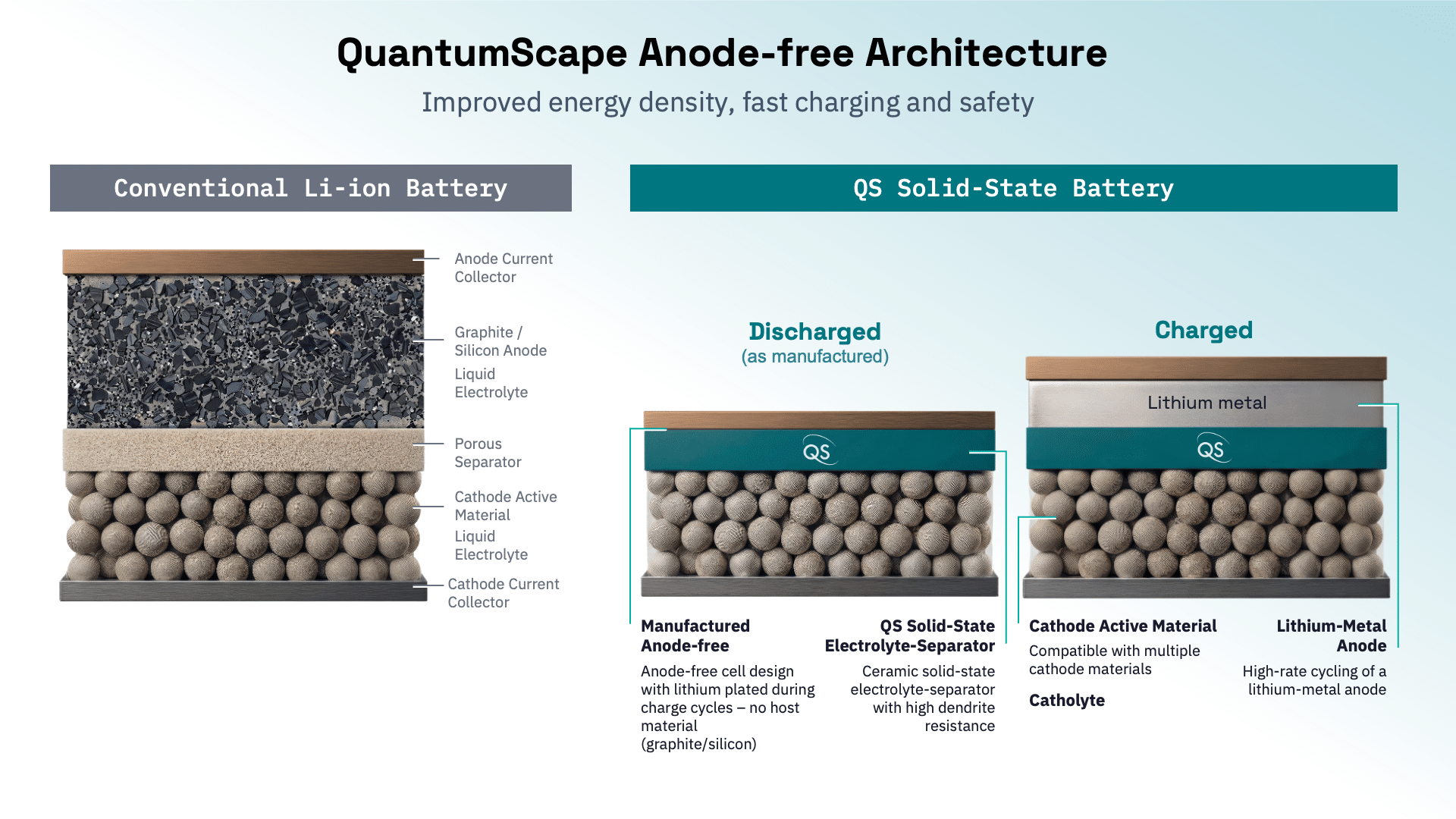
The core of all QS battery technology is our proprietary ceramic separator, manufactured using a continuous-flow process we refer to as the Cobra process. This separator has several important characteristics:
- It is chemically stable with lithium metal, which enables very high Coulombic efficiency, significantly higher than any competing lithium-metal anode cells we are aware of. This enables the use of an anode-free design, with zero excess lithium foil on the anode, while still achieving long cycle life: 1000 cycles under gold-standard testing conditions.
- The interface between the ceramic separator and lithium-metal anode is extremely high quality, eliminating the characteristic “voiding” or “pitting” observed during discharge of other lithium-metal cells and enabling operation at much lower levels of applied pressure (<3.4 atm) than other solid-state approaches.
- It is mechanically strong enough to resist dendrites, root-like protrusions of lithium metal that can pierce polymer- or sulfide-based solid separators and short-circuit the cell, rendering it inoperable and potentially representing a safety hazard.
- It is thermally stable at high temperatures, and safety testing has demonstrated commercial cell designs resisting temperatures of greater than 300 °C without inducing thermal runaway.
The QS ceramic separator replaces the porous separator and eliminates the anode in the battery cell stack, resulting in improved performance and safety relative to conventional cells. On the cathode side, however, the QS separator is technologically cross-compatible.
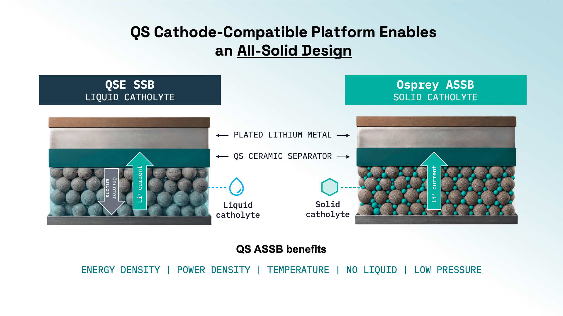
In the current generation of QS technology, the QSE platform, the ceramic separator is paired with a relatively conventional high-nickel NMC cathode and a liquid catholyte. This platform is the basis of the QSE-5, our first commercial product. The QSE platform has many benefits: good low-temperature performance, high discharge power, sub-15-minute fast charging capability, a superior safety profile and high energy density. Nevertheless, different catholyte types offer a unique mix of advantages, and cathodes using solid sulfide catholytes allow us to push the energy-power performance frontier even further, enabling five-minute fast-charging and energy density up to ~1100 Wh/L when combined with the QS ceramic separator.
This is Osprey: an open solid-state platform that allows developers of sulfide-based solid-state batteries to incorporate QS technology into their all-solid-state battery (ASSB) development programs. This allows them the possibility of leveraging their ASSB cathode technology while benefiting from the unique properties of the QS ceramic separator.
Sulfide-based All-Solid-State Batteries (ASSB) – Benefits and Challenges
Sulfide-based solid electrolyte materials remain one of the most popular technology pathways for automotive solid-state battery development. They have several advantageous materials-level characteristics:
- Sulfides are relatively easy to process at low temperatures, which makes certain aspects of manufacturing more practical than other materials.
- They have good ionic conductivity, making them well-suited to high-power applications such as electric vehicles.
- The raw material inputs for sulfide-based electrolytes are relatively inexpensive, though realizing these cost savings requires the industry to reach similar scale to conventional battery materials.
These traits have helped make sulfides a popular candidate for research and development in the solid-state battery industry. As research has progressed over the years, though, sulfide battery developers have found themselves running up against showstoppers: fundamental limitations of sulfide materials that prevent them from being used as separators in a solid-state battery. These limitations include:
Poor Cycle Life
Sulfides face significant challenges when paired with lithium-metal anodes. This is due to the tendency of sulfides to react with lithium, which harms battery lifetime due to poor Coulombic efficiency. To get around this challenge, researchers have tried pairing sulfides with high-performance silicon anode materials. Unfortunately, when such anode host materials are added back into the system, the energy density benefit is reduced or even eliminated, which undermines one of the most important benefits of solid-state batteries.
High Pressure
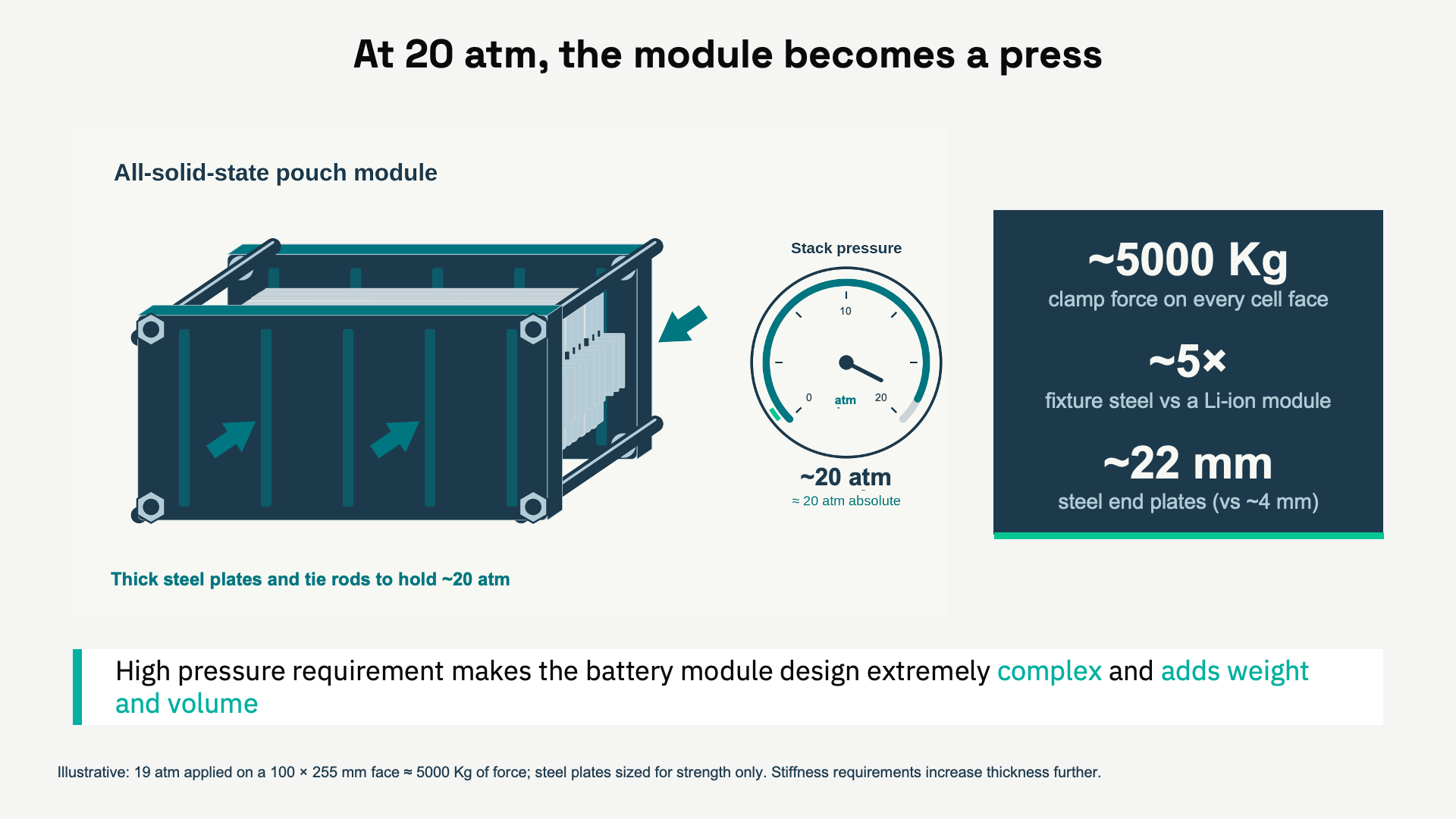
Applied pressure has been another Achilles heel of sulfide separator systems. Over repeated cycling, the sulfide material will tend to lose physical contact with the active materials of the battery. To allow the battery to continue operating, cells with sulfide separators must be kept under pressure. While applying pressure works on a small-scale lab bench, the pressures required are too high to be practical for real-world applications.
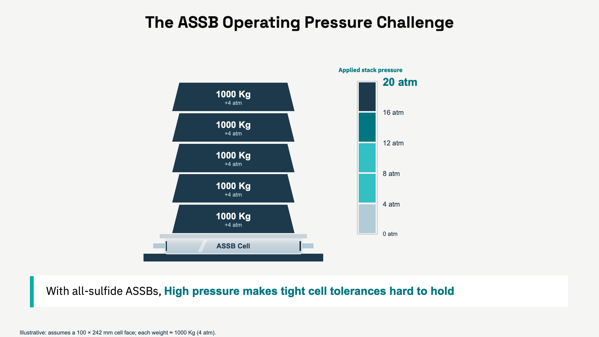
The question is not whether such a pressure device can be manufactured, but how it impacts the final cost, energy density, and reliability of the system as a whole. As the illustration here shows, the forces involved make such a system impractical. The conclusion is straightforward: an automotive solid-state battery cannot require such extreme pressures, and therefore zero or very low-pressure operation is strictly necessary for an automotive cell to be viable.
High Temperature
All-solid-state batteries based on sulfide electrolytes also have not shown very good performance at room temperature and below. Despite good ionic conductivity at room temperature, they have faced challenges with interfacial resistance at the solid-solid interfaces of the solid electrolyte and cathode active material (such as NMC particles) as well as on the anode side at the interface between the solid electrolyte and anode material, such as graphite, silicon or excess lithium metal foil. This has meant that sulfide-based ASSBs typically require elevated temperatures to show good performance.
Slow Charging
Sulfide separators have also not yet demonstrated that they are capable of fast-charging with lithium-metal anodes. This is due to their low critical current density, which relates to the maximum possible charge rate before dendrites begin to form, piercing through the separator and short-circuiting the cell. For more background on critical current density, refer to our 2025 peer-reviewed paper published in the Journal of the Electrochemical Society.
We believe these limitations are not simply engineering challenges but rather represent the fundamental properties of sulfide-based electrolyte materials. The observed rate of progress in the field has borne out this view: despite the best efforts of highly competent and sophisticated battery developers over more than a decade, sulfides still seem to face the same technical challenges. In fact, to the best of our knowledge, the issues raised in our original blog post on the subject five years ago remain unresolved.
However, although sulfide electrolytes may not be suitable as separators, they have benefits as catholytes in a battery with a different kind of separator: one that is thermally stable, resistant to dendrites, chemically compatible with pure lithium metal, and capable of operating without applied pressure. This is exactly the set of properties offered by the QS ceramic separator.
Benefits of Sulfide Catholytes
The unique properties of sulfides offer several potential performance benefits to the QS platform that we believe could be highly valuable to a wide variety of applications, including automotive.
First, unlike a liquid catholyte, sulfides are single-ion conductors. This means that ions travel from the cathode active material (CAM), through the molecular structure of the sulfide, and into the separator via ion hopping. Imagine it like a single-file line: When one lithium ion leaves the front of the line and passes through the separator, all the ions behind it move up a step, and another ion enters the line at the back.
Compare this to a liquid, where lithium ions exit the CAM and enter a liquid solution of both positively charged lithium ions and negatively charged anions. The positively charged ions have to “swim upstream” against the negatively charged anions. This creates a traffic jam of lithium ions near the CAM particles.
Why use a solid electrolyte?
Solid electrolytes enable more efficient ion transport, unlocking faster charge & discharge
This traffic jam process, known as polarization, represents a limit to how fast the battery can be charged. Although lithium-ion batteries can be engineered to optimize for higher charge rates, all liquid-based systems experience polarization. In contrast, this lack of polarization is one of the most attractive benefits of sulfides and can potentially lead to much faster charging times, as low as five minutes.
Why use a solid catholyte?
Solid electrolytes enable more efficient ion transport, unlocking faster charge & discharge
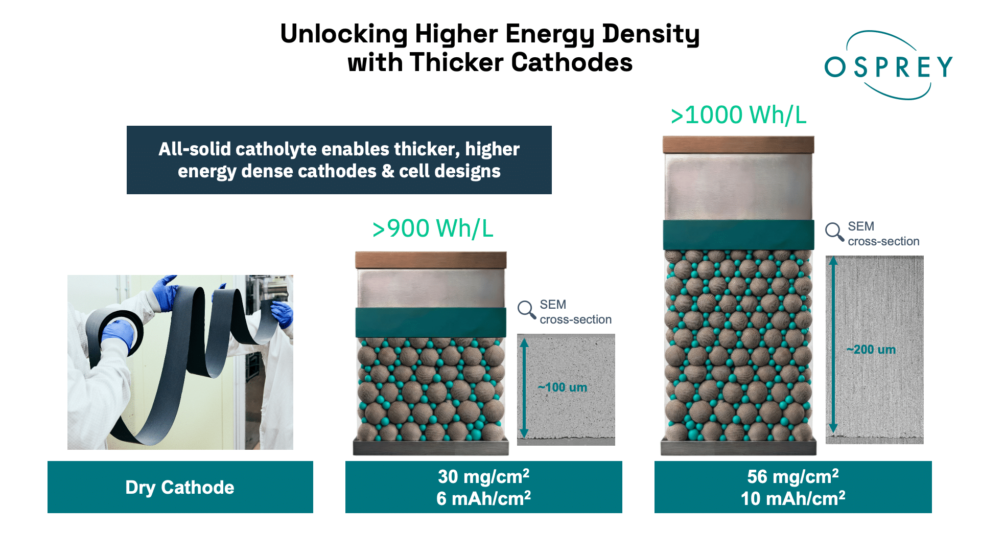
In addition to fast charging, sulfides gain another potential benefit from being single-ion conductors. Because there is no polarization, they could potentially be used to make cathodes much thicker than would be possible in a liquid-catholyte system. For context, a typical lithium-ion battery has a cathode loading of between 3 and 5 mAh/cm2. Our development work has shown that a sulfide-based catholyte could enable a cathode loading of 10 mAh/cm2, roughly twice as high. This would allow each battery cell to use fewer layers to achieve a given capacity, eliminating extra separators and current collectors and making the whole battery more energy dense. This boost in energy density is another prize of sulfide integration on the Osprey platform.
One additional benefit of sulfides is the significant amount of R&D and manufacturing scale-up investment by the larger solid-state battery industry. Companies across the value chain have made significant progress in materials development, materials manufacturing, electrode manufacturing, CAM design, and a whole host of technical challenges. However, these efforts have been somewhat fragmented, and they have all run against the same fundamental limitations of sulfides as separators.
The Benefits of the Osprey Platform
That’s why our frontier R&D team at QS has developed Osprey: an open solid-state platform for all-solid-state battery development that pairs the QS ceramic separator with cathodes using solid sulfide catholytes. Osprey cells are all-solid-state cells that are anode-free as manufactured and store energy as pure lithium metal.
The Osprey platform consists of three components: the QS ceramic separator, the solid cathode with sulfide catholyte, and the process by which those two physical components can be assembled into an all-solid-state battery. It is well understood that such a system faces technical challenges such as interfacial resistance at the boundary between solid electrolyte materials, and these are challenges our team has had to understand and address to generate the data shared here.
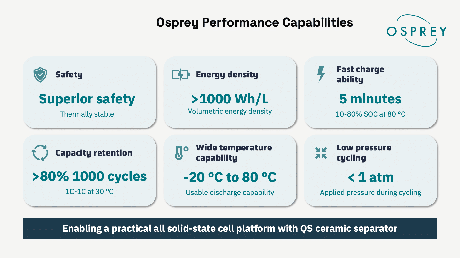
For the first time in this whitepaper, we are publishing performance results from Osprey cells that demonstrate long cycle life: 1000 cycles to 80% capacity retention under gold-standard testing conditions, five-minute fast charging, low-temperature operation (down to -20 °C) and high-temperature thermal stability, while requiring no more than approximately 1 atm of pressure. We project that, enabled by high-loading cathodes, large-format Osprey cells could reach energy densities up to ~1100 Wh/L.
Osprey addresses the core challenges of sulfide electrolyte systems by combining the QS ceramic separator with a sulfide-based solid cathode. We believe the Osprey platform offers performance results that are unmatched by any other sulfide-based system published to date and is a fundamental breakthrough in all-solid-state battery performance.
Long Cycle Life at Low Pressure
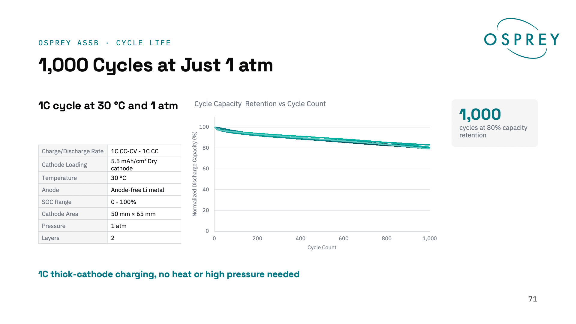
Osprey cells have shown stable cycling at 1 atm of applied pressure, eliminating the need for complex pressure application devices at the system level. Osprey cells show 1000 cycles to 80% capacity retention under gold-standard testing conditions: 1C/1C cycling, 100% depth of discharge, room temperature, 1 atmosphere of pressure, all in a 2-layer unit cell with commercially relevant area and cathode loading. To the best of our knowledge, no other sulfide-based solid-state cell has ever demonstrated this capability.
Five-Minute Fast Charging
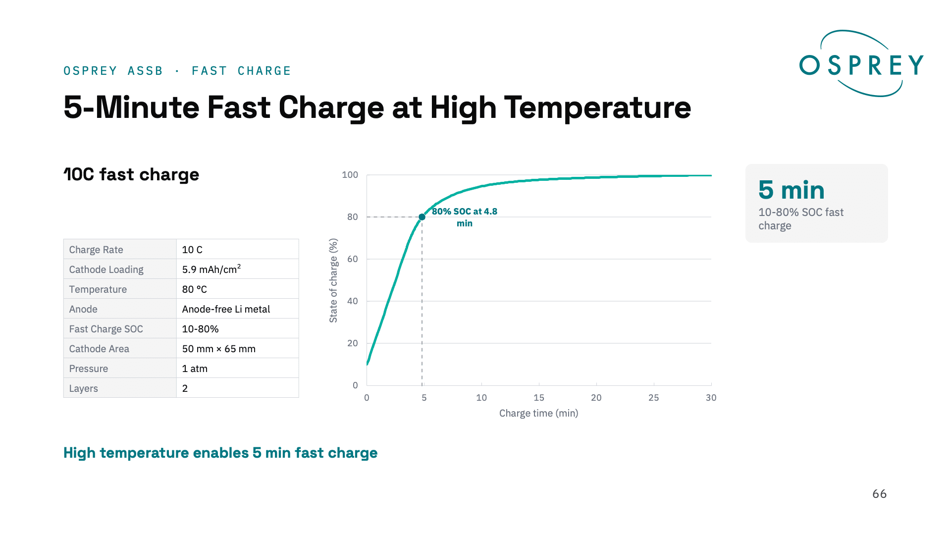
Since the QS ceramic separator demonstrates such high critical current density, it can overcome the fast-charging limitations of sulfide materials. Osprey cells have shown fast-charging from 10-80% in approximately five minutes with commercially relevant cathode loadings and over a commercially relevant cell area.
Low-Temperature Operation
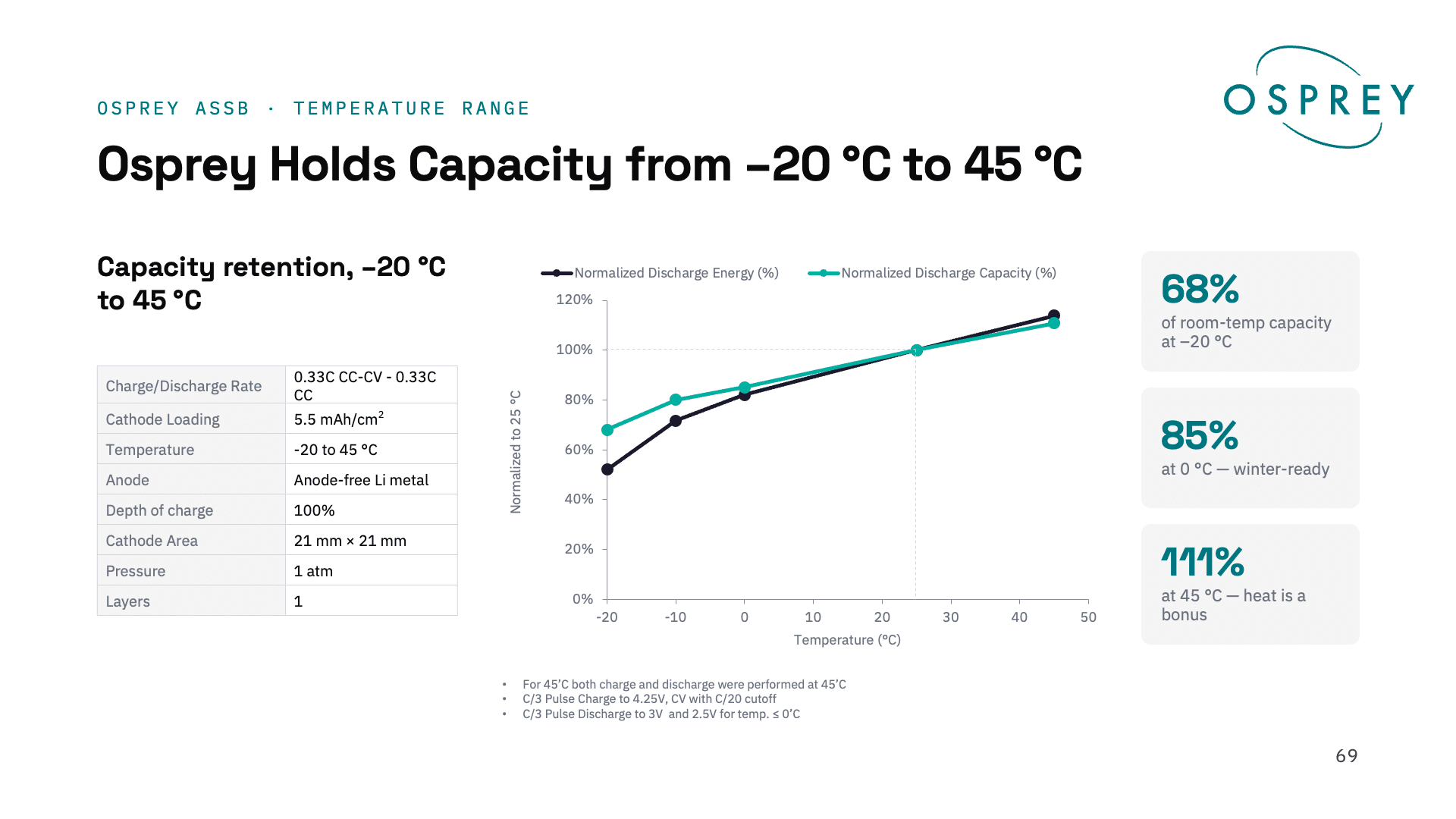
Osprey cells demonstrate the fundamental ability to maintain accessible capacity down to -20 °C, which has been a significant challenge for sulfide-based systems.
Thermal Stability
Due to the unique safety profile of the QS ceramic separator, Osprey cells are thermally stable at high temperatures. As with our QSE platform, this indicates an improved safety profile relative to conventional lithium-ion batteries, and the presence of the non-flammable, non-combustible ceramic separator is an improvement over sulfide-based separators, which are not stable against lithium metal.
Higher Cathode Loading
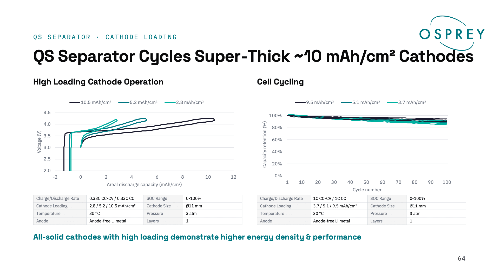
Due to the single-ion conductor property of sulfide electrolytes, extremely high cathode loadings of 10 mAh/cm2 are possible. In benchtop testing, these high-loading cathodes show similar cycling performance to lower loadings. This high loading is enabled by a QS-proprietary dry process; this dry cathode can be handled in roll form, and the free-standing cathode can then be laminated onto the cathode current collector, providing a potential pathway for scalable manufacturing.
Shifting the Energy-Power Frontier
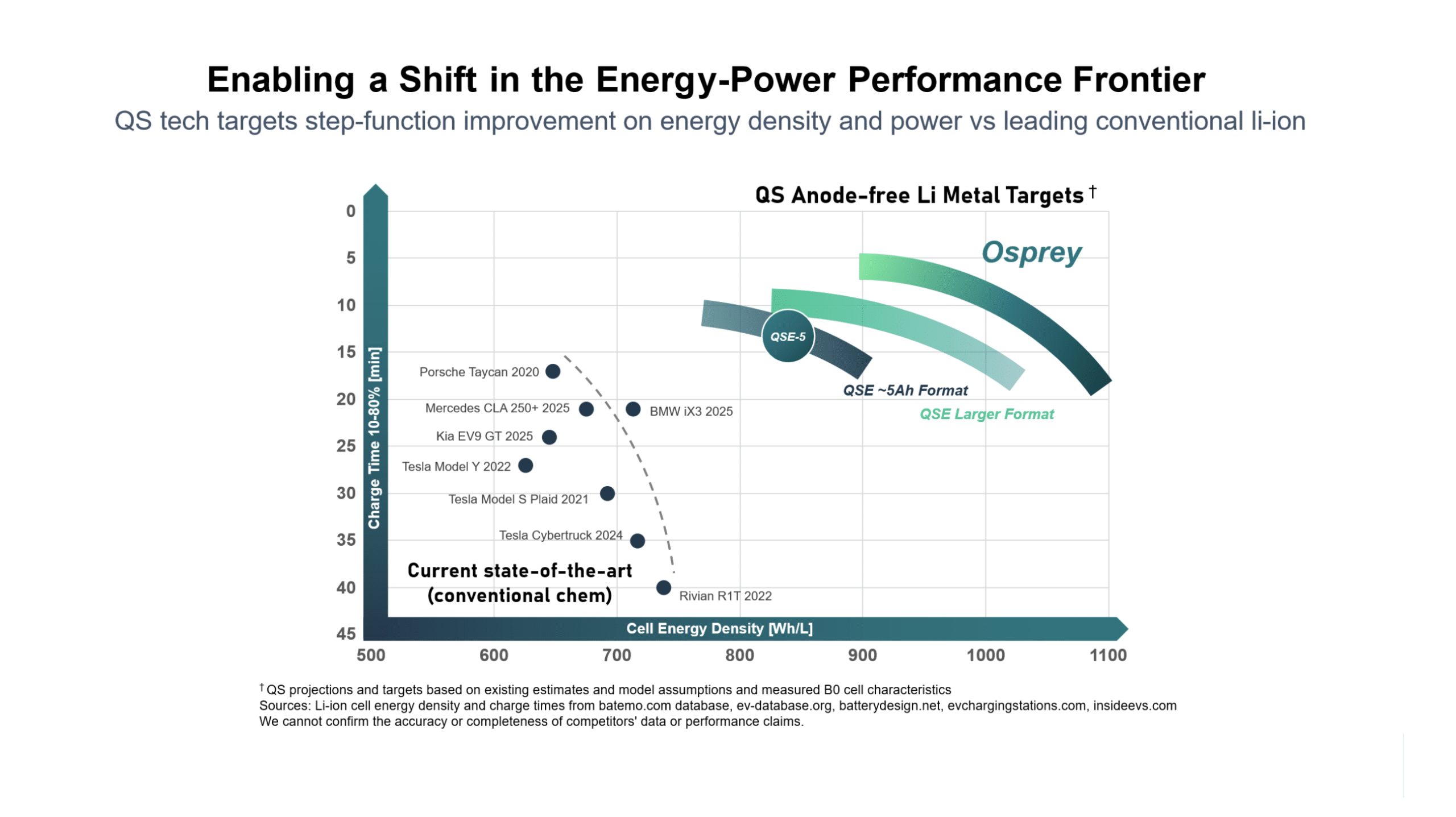
All lithium-ion batteries have to optimize a tradeoff between energy density and fast-charging capability. Osprey offers a combination of performance benefits that allow QS cells to push the frontier of battery performance further, enabling five-minute fast charging in a power-optimized cell and energy density up to ~1100 Wh/L in an energy-optimized design.
Next Steps
Engagement with our Osprey customers begins in the early stages of cell development. Whereas our QSE platform is currently being scaled up to mass production as a full-stack technology solution, Osprey presents a fundamentally collaborative model for all-solid-state battery development. Customers that prefer a sulfide-based cathode may choose to use our QS-proprietary sulfide-based cathode technology, or they have the option of bringing their own cathode to the Osprey platform. This allows them to leverage their own cathode technology, materials and supply chain while gaining the benefits of the QS ceramic separator.
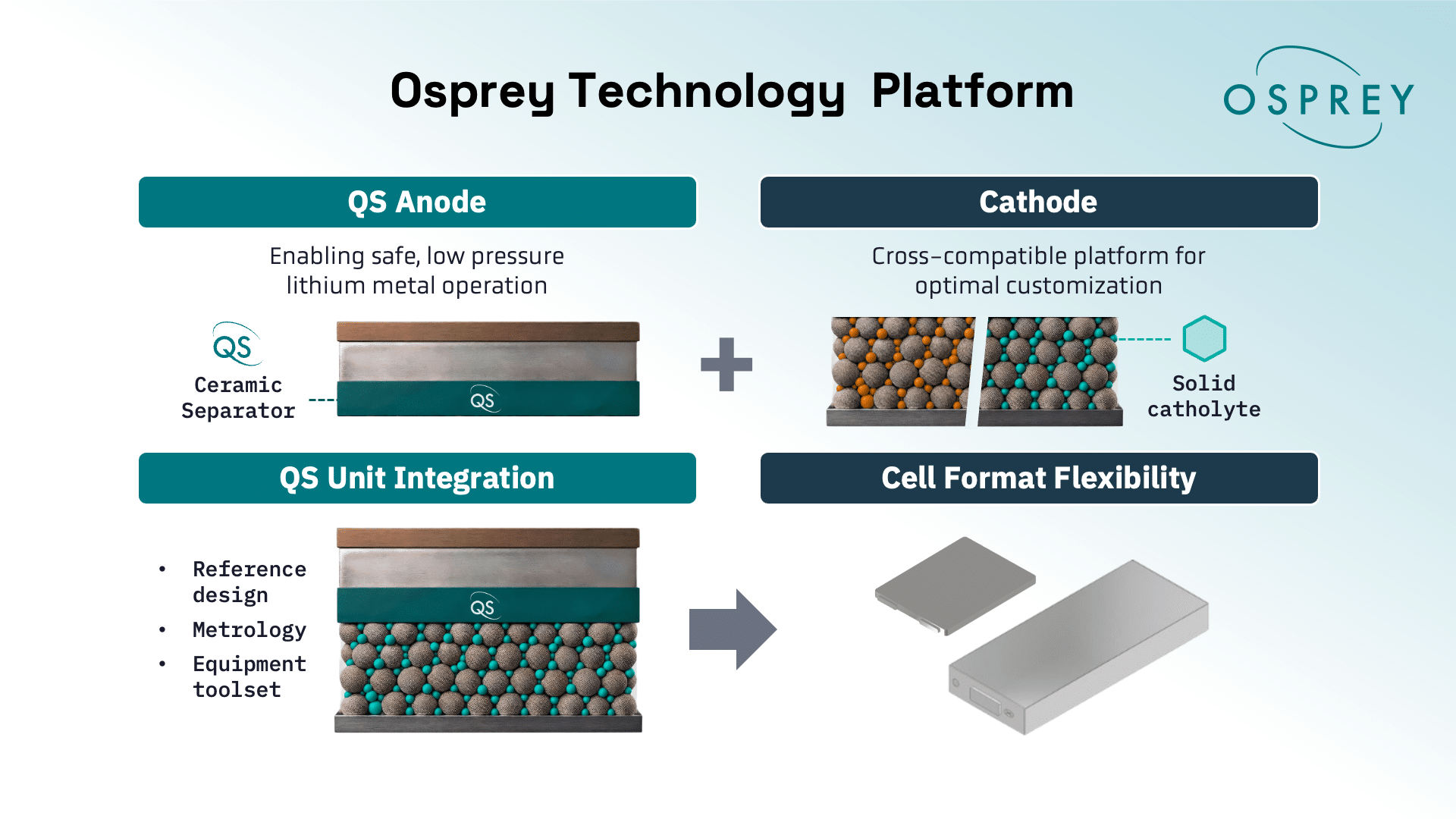
There are engineering and development challenges remaining before Osprey is mature enough for mass-production scale. For example, our automotive customers generally prefer to work with larger-format prismatic cells that offer more capacity than the QSE-5 design. The results shown here are primarily from building-block 2-layer unit cells that demonstrate the fundamental stack chemistry of the Osprey platform in cells with the same area as our QSE-5 cell design, but larger cells will likely require both more layers and more area per layer. We will work closely with our Osprey customers to co-design cells that meet their requirements.
In addition, the fundamental process to build Osprey cells has been demonstrated at laboratory scale, and higher-throughput processes are in the development stage. A major advantage of the Osprey platform is that significant R&D has already been done on manufacturing solid cathodes with sulfide-based solid electrolytes. Osprey can leverage this investment while eliminating the need for further development work on sulfide separators or anodes. As the engineering adage goes, the best part is no part: QS cells are anode-free by design, and Osprey allows sulfide battery developers to gain the benefits of the QS anode-free architecture.
We are partnering with world-leading automotive OEMs and building on the work that has already been done to scale up sulfide cathode production. We have demonstrated the fundamental techniques to make Osprey cells at a lab scale, but significant work remains in process engineering to increase the speed and scale of the core Osprey process.
Conclusion
Osprey is designed as an open platform that enables the QS ceramic separator to serve as an enabling technology for the broader all-solid-state battery market, offering the potential to overcome previously intractable problems posed by sulfide-based systems. As we have demonstrated, it can elevate the performance of solid sulfide cathodes, and therefore we believe it represents a best-in-class solution for solid-state separator and anode, regardless of cathode type. From a big-picture perspective, Osprey represents a pathway for broad cooperation in the highly competitive race to develop commercial ASSB technology.
Forward-Looking Statements
This publication contains forward-looking statements within the meaning of the federal securities laws. All statements other than statements of historical fact contained in this publication, including statements regarding QuantumScape’s technology roadmap; the future development, performance, safety and anticipated benefits of its technologies, products and manufacturing processes; the results of testing and demonstrations, including in real-world applications; potential markets, applications and use cases; its strategy, business model, anticipated milestones, and plans for licensing, partnerships, collaborations and its ecosystem; the timing of commercialization and scale-up; and industry trends, estimates of addressable markets, and expected demand for batteries and the value thereof, are forward-looking statements. When used in this publication, the words “aim,” “allow,” “anticipate,” “believe,” “blueprint,” “can,” “committed,” “continue,” “could,” “designed to,” “enable,” “estimate,” “expect,” “focus,” “forecast,” “future,” “goal,” “going forward,” “intend,” “may,” “offers,” “opportunity,” “outlook,” “permit,” “plan,” “position,” “potential,” “predict,” “project,” “prospective,” “roadmap,” “seek,” “should,” “strategy,” “target,” “up to,” “will,” “work toward,” “would,” and the negative of such terms and other similar expressions are intended to identify forward-looking statements, although not all forward-looking statements contain such identifying words.
These forward-looking statements are based on management’s current expectations, assumptions, hopes, beliefs, intentions, and strategies regarding future events and are based on currently available information as to the outcome and timing of future events. They are not guarantees of future performance and involve significant risks and uncertainties that could cause the actual results to differ materially from the expected results, including risks related to technology development and scale-up, production, commercialization, partnerships and licensing, entry into new markets, costs and financing, trade and geopolitical conditions, competition, and intellectual property. Many of these factors are outside QuantumScape’s control and are difficult to predict. Performance demonstrated in sample cells or in internal, customer, or third-party testing may not be replicated at scale or in commercial products. QuantumScape cautions readers and viewers not to place undue reliance upon any forward-looking statements, which speak only as of the date made. Except as otherwise required by applicable law, QuantumScape disclaims any duty to update any forward-looking statements. Should underlying assumptions prove incorrect, actual results and projections could differ materially from those expressed in any forward-looking statements. Additional information concerning these and other factors that could materially affect QuantumScape’s actual results can be found in the “Risk Factors” section of QuantumScape’s most recent Annual Report on Form 10-K and subsequent Quarterly Reports on Form 10-Q, as well as its other filings with the SEC, which are available on the SEC’s website at www.sec.gov.